- 您现在的位置:买卖IC网 > Sheet目录3891 > PIC16C622A-40/SS (Microchip Technology)IC MCU OTP 2KX14 COMP 20SSOP
13
AT90S1200
0838H–AVR–03/02
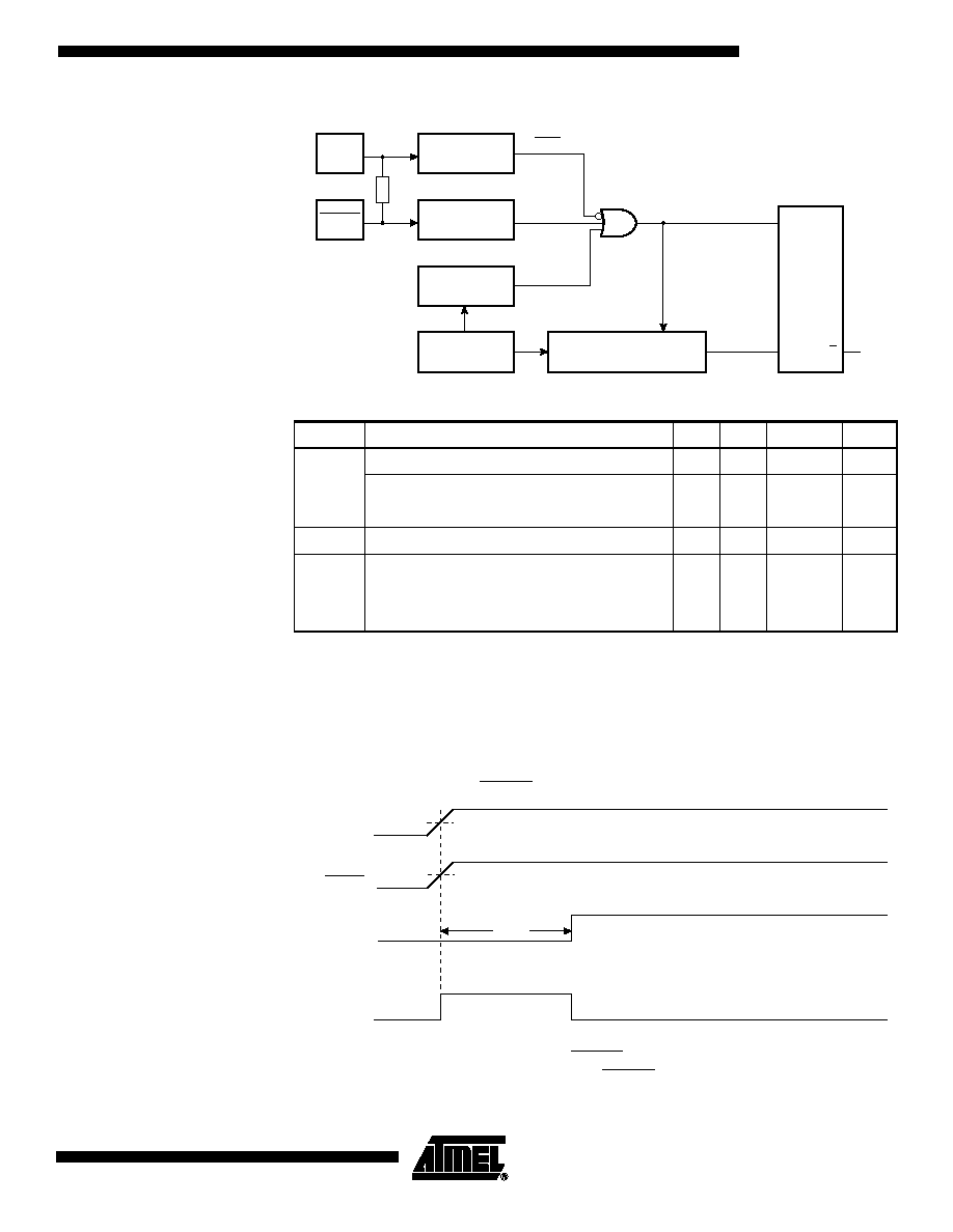
Figure 13. Reset Logic
Note:
1. The Power-on Reset will not work unless the supply voltage has been below VPOT
(falling).
Power-on Reset
A Power-on Reset (POR) circuit ensures that the device is reset from power-on. As
shown in Figure 13, an internal timer clocked from the Watchdog timer oscillator pre-
vents the MCU from starting until after a certain period after VCC has reached the Power-
Figure 14. MCU Start-up, RESET Tied to VCC.
If the built-in start-up delay is sufficient, RESET can be connected to V
CC directly or via
an external pull-up resistor. By holding the RESET pin low for a period after V
CC has
Table 3. Reset Characteristics (V
CC = 5.0V)
Symbol
Parameter
Min
Typ
Max
Units
VPOT
Power-on Reset Threshold Voltage (rising)
0.8
1.2
1.6
V
Power-on Reset Threshold Voltage (falling)
0.2
0.4
0.6
V
VRST
Pin Threshold Voltage
––
0.85 VCC
V
tPOR
Power-on Reset Period
2.0
3.0
4.0
ms
tTOUT
Reset Delay Time-out Period (The Time-out
period equals 16K WDT cycles. See “Typical
Characteristics” on page 51. for typical WDT
frequency at different voltages).
11.0
16.0
21.0
ms
VCC
Power-on Reset
Circuit
RESET
POR
100 - 500K
Reset Circuit
Watchdog
Timer
On-chip
RC Oscillator
Counter
Reset
14-stage Ripple Counter
Time-out
S
Q
R
Q
Inter
nal
Reset
VCC
RESET
TIME-OUT
INTERNAL
RESET
t
TOUT
V
POT
V
RST
发布紧急采购,3分钟左右您将得到回复。
相关PDF资料
PIC16CE623-30/SO
IC MCU OTP 512X14 EE COMP 18SOIC
PIC16CE624-30/SO
IC MCU OTP 1KX14 EE COMP 18SOIC
PIC16CE624-30/SS
IC MCU OTP 1KX14 EE COMP 20SSOP
PIC16CE623-30/SS
IC MCU OTP 512X14 EE COMP 20SSOP
PIC16CE624-30/P
IC MCU OTP 1KX14 EE COMP 18DIP
PIC16F722-I/SO
IC PIC MCU FLASH 2KX14 28-SOIC
PIC16F677-I/SO
IC PIC MCU FLASH 2KX14 20SOIC
PIC18LC601-I/PT
IC MCU ROMLESS A/D PWM 64TQFP
相关代理商/技术参数
PIC16C622AT-04/SO
功能描述:8位微控制器 -MCU 3.5KB 128 RAM 13 I/O RoHS:否 制造商:Silicon Labs 核心:8051 处理器系列:C8051F39x 数据总线宽度:8 bit 最大时钟频率:50 MHz 程序存储器大小:16 KB 数据 RAM 大小:1 KB 片上 ADC:Yes 工作电源电压:1.8 V to 3.6 V 工作温度范围:- 40 C to + 105 C 封装 / 箱体:QFN-20 安装风格:SMD/SMT
PIC16C622AT-04/SS
功能描述:8位微控制器 -MCU 3.5KB 128 RAM 13 I/O RoHS:否 制造商:Silicon Labs 核心:8051 处理器系列:C8051F39x 数据总线宽度:8 bit 最大时钟频率:50 MHz 程序存储器大小:16 KB 数据 RAM 大小:1 KB 片上 ADC:Yes 工作电源电压:1.8 V to 3.6 V 工作温度范围:- 40 C to + 105 C 封装 / 箱体:QFN-20 安装风格:SMD/SMT
PIC16C622AT-04E/SO
功能描述:8位微控制器 -MCU 3.5KB 128 RAM 13 I/O RoHS:否 制造商:Silicon Labs 核心:8051 处理器系列:C8051F39x 数据总线宽度:8 bit 最大时钟频率:50 MHz 程序存储器大小:16 KB 数据 RAM 大小:1 KB 片上 ADC:Yes 工作电源电压:1.8 V to 3.6 V 工作温度范围:- 40 C to + 105 C 封装 / 箱体:QFN-20 安装风格:SMD/SMT
PIC16C622AT-04E/SS
功能描述:8位微控制器 -MCU 3.5KB 128 RAM 13 I/O RoHS:否 制造商:Silicon Labs 核心:8051 处理器系列:C8051F39x 数据总线宽度:8 bit 最大时钟频率:50 MHz 程序存储器大小:16 KB 数据 RAM 大小:1 KB 片上 ADC:Yes 工作电源电压:1.8 V to 3.6 V 工作温度范围:- 40 C to + 105 C 封装 / 箱体:QFN-20 安装风格:SMD/SMT
PIC16C622AT-04I/SO
功能描述:8位微控制器 -MCU 3.5KB 128 RAM 13 I/O RoHS:否 制造商:Silicon Labs 核心:8051 处理器系列:C8051F39x 数据总线宽度:8 bit 最大时钟频率:50 MHz 程序存储器大小:16 KB 数据 RAM 大小:1 KB 片上 ADC:Yes 工作电源电压:1.8 V to 3.6 V 工作温度范围:- 40 C to + 105 C 封装 / 箱体:QFN-20 安装风格:SMD/SMT
PIC16C622AT-04I/SS
功能描述:8位微控制器 -MCU 3.5KB 128 RAM 13 I/O RoHS:否 制造商:Silicon Labs 核心:8051 处理器系列:C8051F39x 数据总线宽度:8 bit 最大时钟频率:50 MHz 程序存储器大小:16 KB 数据 RAM 大小:1 KB 片上 ADC:Yes 工作电源电压:1.8 V to 3.6 V 工作温度范围:- 40 C to + 105 C 封装 / 箱体:QFN-20 安装风格:SMD/SMT
PIC16C622AT-20/SO
功能描述:8位微控制器 -MCU 3.5KB 128 RAM 13 I/O RoHS:否 制造商:Silicon Labs 核心:8051 处理器系列:C8051F39x 数据总线宽度:8 bit 最大时钟频率:50 MHz 程序存储器大小:16 KB 数据 RAM 大小:1 KB 片上 ADC:Yes 工作电源电压:1.8 V to 3.6 V 工作温度范围:- 40 C to + 105 C 封装 / 箱体:QFN-20 安装风格:SMD/SMT
PIC16C622AT-20/SS
功能描述:8位微控制器 -MCU 3.5KB 128 RAM 13 I/O RoHS:否 制造商:Silicon Labs 核心:8051 处理器系列:C8051F39x 数据总线宽度:8 bit 最大时钟频率:50 MHz 程序存储器大小:16 KB 数据 RAM 大小:1 KB 片上 ADC:Yes 工作电源电压:1.8 V to 3.6 V 工作温度范围:- 40 C to + 105 C 封装 / 箱体:QFN-20 安装风格:SMD/SMT